2009 Jeep Cherokee Coolant High Temp Light Reads High Then Goes Back to Normal
At that place are a lot of error codes that signal to Jeep Grand Cherokee WJ transmission malfunctions and limp style. You tin study the list provided below. Addition to those mentioned, also P1242 , P2210 and P2212 may occur due to data communication errors which result from cleaved Jeep gear shifter (mostly), Transmission Command Module (TCM) or wiring betwixt Engine Control Unit (ECU) and TCM.
It is possible to fix the gear shifter, but you would demand difficult-to-go microchips and it can pause again soon due to oxidation.
Below y'all can detect some virtually common faults that may be related to fault lawmaking P0702.
one. P2602 Solenoid Valve: ability supply Value/signal exterior range.
This error is very common, it means that transmission solenoids are non getting enough power. With this code there can be ii reasons – gearbox plug adapter or weak battery. Well-nigh gearbox plug adapter y'all can look at tip 4. If adapter is fine, then your car has a weak battery and y'all need to change information technology. Yous tin can also avoid bombardment fault by request Jeep dealer to upgrade TCM software. Upgrading software does not make your battery new, it only does not permit your automobile to get into limp way for this error. Until you tin can't start your automobile on a cold winter morning as you bombardment is notwithstanding weak…
2. Gear shifter lever, OEM codes 52104468AJ, 52104468AC, 52104468AD, 52104468AE, 52104468AF, 52104468AG, 52104468AH, 52104468AI
These are the almost mutual and expensive faults that tin can lead to P0702. You have to replace the Gear Shifter Lever PCB Board.
3. Weak battery or bad battery connectors.
Your Jeep Grand Cherokee'southward transmission can go into limp mode if you are using a weak battery. You lot should cheque the battery and cables from both ends, battery and machine. If the limp mode is caused by bad battery then you can upgrade the Manual Control Module software at your dealer. This upgrade won't make your battery better, only does not permit TCM to go into limp style cause of undervoltage. To avoid starting problems in futurity, yous should notwithstanding change the bombardment soon.

four. Gearbox plug adapter, OEM 68021352AA
Manual plug adapter is located under the car and often starts leaking oil. Once oily, the plugs have bad electrical connexion and transmission goes into limp fashion and starts showing fault codes. It is like shooting fish in a barrel to check the plug – await under the car and check if the plug is oily. If it's oily – get it replaced. Besides check if the cables are fine – with fourth dimension the isolation tin can crack and cables tin can get to brusk excursion. Then the outcome is over again P0702 and limp mode. Yous can easily fix information technology with some tape.
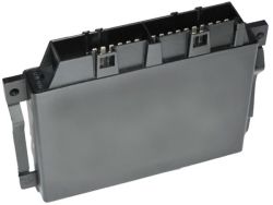
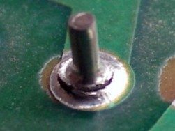
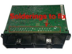
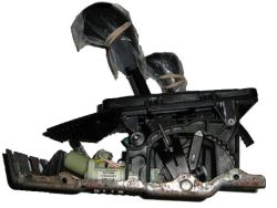
v. Bad solderings in TCM.
The solderings of the plugs of Transmission Control Module can scissure with fourth dimension. Disassemble the TCM and use magnifier to cheque the solderings of both plugs. If you can see any circles on the solderings so resolder them. You can resolder them for "simply in case" equally well. TCM is located on the correct side of shifter assembly, about the rider legs.

six. Transmission Valve Trunk Electrical Plate, OEM codes: 1402700161, 1402700361, 1402700561, 1402700761, 1402700861, 1402701161
In that location are some sensors in this plate and if your vehicle is showing the codes P0715 and P0720, this is nigh likely your problem. This plate is located inside the gearbox, only replacing information technology is not difficult.

7. Different fault codes when ECU cables has cleaved by steering shaft
One reason tin be cleaved cablevision fastening – the cable has moved from its right position and rubs against other parts. Check in engine bay nether the battery if the steering shaft frictions the cables coming from Engine Command Module. Yous can check information technology with a mirror that is attached to a long rod. You need to cheque if the fastening of the bundle of cables is intact and that they take not been rubbing confronting the steering shaft. Equally there is lot of cables in this place, then can be dissimilar fault codes – data bus, sensors, power etc. If you can check your engine fault codes then you can exercise this – delete all faults from engine, and so start your machine and turn steering wheel to left and correct. If this makes the code to render, and so it is your wiring that is cleaved. To fix this you'll need to have off the bombardment, the plate nether the battery and isolate/fix the broken wiring. You should also await at this identify when you have another incomprehensible electrical issue and you lot can not observe reason for it.
8. Fault code P0836 caused past Transfer case position sensor, OEM 5083138AA
P0836 is also very common transmission mistake. Information technology makes MIL lite on and car will be in limp mode. Trouble is Transfer case position sensor or it'due south wiring. Y'all tin check sensor, oxidation of ECU (in engine bay on driver side) pin no. 29 and wire betwixt ECU and sensor.
9. Fault code P0700 is caused by solenoids
P0700 is too transmission electrical fault, just information technology is related with transmission solenoids and if you have this lawmaking instead of P0702, so you should look at solenoids, TCM or wiring between them.

10. No gear position lights on shifter and no fault codes.
If there is no yellow position lights on shifter, then in most cases shifter board is cleaved. Just in case you can check at shifter board input voltage. Measure voltage on shifter board main socket plug, pin 1 is +12V and pin 11 is ground. If y'all get +12V from those plug pins with ignition on, then fuses and wiring are fine and shifter board is cleaved. If in that location is not +12V, and then you should look at fuse F12 on top of commuter legs and wiring betwixt fuse box and shifter lath. Electricity coming from battery>fuse cake>shifter board>TCM. If power is cut somewhere, then TCM may not have error codes since TCM does not get +12V and is switched off.
Your Jeep Grand Cherokee can besides become to the limp fashion due to ABS control unit of measurement located in engine bay. Yous can check this with proper diagnostics device.
We will be happy to help yous in identifying the errors, however, for this nosotros need to know all the engine and TCM fault codes readed by proper diagnostics device. Ignition ON/OFF method shows just engine mistake codes and we can not provide an acceptable respond without TCM fault codes.
Retrieving ECU fault codes:
Turn the ignition key until the digital odometer displays, repeat iii times in succession and then back to "On" (On/Off, On/Off, On/Off, On). At the fourth "On" the odometer will be replaced with codes.
With key on-off method you can simply run into engine ECU faults. For TCM faults you'll need a proper diagnostics device every bit DRB III or Bosch KTS. Those devices are very expensive and we made a complimentary program for reading/immigration engine and transmission faults for 2.7 Jeep One thousand Cherokee. It works with ELM327 based diagnostic device, you tin can get it from ebay for five EUR. Check at our software folio.
Jeep Chiliad Cherokee WJ two.7 CRD limp modes and MIL illumination.
Permanent limp-in mode.
When the TCM determines in that location is a non-recoverable condition present that will not allow proper transmission operation, it will place the transmission in permanent limp-in way. When the condition occurs the TCM will turn off all solenoids as well as the solenoid supply output excursion. If this occurs while the vehicle is moving, the transmission will remain in the electric current gear until the ignition is turned off or shifter is placed in the P position. Once the shifter has been placed in P the Transmission volition but let 2d gear performance. . If the trouble occurs while the vehicle is non moving the manual volition only allow 2nd gear operation.
Temporary limp-in mode.
This mode is the same every bit the permanent limp-in mode except if the status is no longer nowadays the system will resume normal performance. (Recoverable DTC)
Undervoltage limp-in fashion.
When the TCM detects that system voltage has dropped below viii.5 volts it will disable voltage dependant diagnostics and place the transmission in the temporary limp-in mode. When the TCM senses that the voltage has risen above nine.0 volts, normal transmission operation will exist resumed.
Hardware Error Mode.
When the TCM detects a major internal error the transmission volition exist placed in the permanent limp-in manner and finish all communication over the CAN bus. Once the TCM has entered this style normal transmission operation will not resume until all DTC's are cleared from the TCM.
Loss of Drive.
If the TCM detects a state of affairs that has resulted or may result in a catastrophic engine or transmission failure, the transmission will exist placed in the neutral position. Improper Ratio, Input Sensor Overspeed, or Engine Overspeed DTC'south will crusade the loss of bulldoze.
Controlled Limp-in Mode.
When a failure condition does not require the TCM to shut down the solenoid supply, only the failure is of a caste where the TCM will place the transmission into a predefined gear, there will be several shift performance issues. Examples of this are, with the transmission slipping the controller volition endeavour to place the transmission into third gear and maintain third gear for all frontward drive weather condition. Another instance is some of the CAN jitney message issues if the TCM does not receive required data from the Engine Controller, and then default values are used which may event in poor transmission shift performance.
MIL ILLUMINATION.
For failures detected by the Transmission Controller that result in the controller placing the transmission into a limp-in mode, except for System Overvoltage and System Undervoltage DTCs, the MIL will exist illuminated. The Transmission Controller will inform the PCM/ECM over the CAN bus that a failure has occurred. The PCM/ECM volition store one of two DTC's P0700 or P0702 depending on which manual DTC is present and volition illuminate the MIL. If the condition is removed and the failure becomes Stored (Intermittent), the Transmission controller will cease reporting that the DTC is active and the PCM/ECM will extinguish the MIL.
Note: The MIL will light when the problem is beginning detected and information technology will not go off until the next ignition cycle, after all problem conditions have been checked for their presence. This normally takes several minutes of driving.
Here is listed manual fault codes for Jeep Grand Cherokee WJ with brusque mistake explanations of possible causes.
| Transmission fault codes | ||
| Bosch KTS lawmaking | DRB 3 ID code | Explanation |
| P2000 | ID 58 | Internal Controller |
| P2001 | ID sixty | Internal Controller |
| P2002 | ID 59 | Internal Controller |
| P2003 | ID 61 | Internal Controller |
| P2004 | ID 57 | Internal Controller |
| P2005 | ID 62 | Internal Controller |
| P2006 | ID 66 | Internal Controller |
| P2007 | ID 67 | Internal Controller |
| P2008 | ID 63 | Internal Controller |
| P200A | ID 65 | Internal Controller |
| P200B | ID 68 | Internal Controller |
| P200C | ID 69 | Internal Controller |
| P2010 | ID 48 | Internal Controller |
| P2011 | ID 47 | Internal Controller |
| P2012 | ID 46 | Internal Controller |
| P2013 | ID 56 | Solenoid Supply/Watchdog |
| P2100 | ID 02 | Solenoid valve, gearbox shift 1-two or 4-v is faulty |
| P2101 | ID 71 | Solenoid valve, gearbox shift 1-ii or 4-v is faulty |
| P2102 | ID 03 | Solenoid valve, gearbox shift 2-three is faulty |
| P2103 | ID 72 | Solenoid valve, gearbox shift 2-3 is faulty |
| P2104 | ID 04 | Solenoid valve, gearbox shift 3-four is faulty |
| P2105 | ID 73 | Solenoid valve gearbox shift 3-4 is faulty |
| P2106 | ID 05 | Torque Converter lockup PWM solenoid valve is faulty |
| P2107 | ID 06 | Modulating force per unit area control solenoid valve is faulty |
| P2108 | ID 07 | Shift pressure control solenoid valve is faulty |
| P2109 | ID 08 | Park lockout solenoid valve is faulty |
| P210A | ID 09 | Park/Neutral output circuit |
| P2200 | ID 12 | Transmission speed sensor 2 defective circuit / open up circuit / short excursion |
| P2203 | ID 13 | Transmission speed sensor 3 defective circuit / open excursion / short circuit |
| P220A | ID 14 | Deviation betwixt transmission input and output speed sensors |
| P220B | ID 15 | Input Sensor Overspeed |
| P2210 | ID 17 | Shifter signal invalid |
| P2211 | ID eighteen | Shifter betoken missing |
| P2212 | ID 76 | Internal Shifter failure |
| P2220 | ID twenty | Manual Temp sensor Shorted |
| P2221 | ID 74 | Park/Neutral switch circuit or Transmission oil temperature sensor indicate improbable |
| P2222 | ID 75 | Transmission oil temperature sensor erratic |
| P2300 | ID 37 | Can communication is faulty |
| P2310 | ID 38 | ABS Tin can messages missing |
| P2311 | ID 39 | Tin communication with the Engine Control Unit not plausible |
| P2312 | ID 36 | CAN bespeak from Engine Control Unit faulty |
| P2315 | ID 35 | CAN signal from Engine Control Unit of measurement faulty |
| P2330 | ID 81 | ABS Tin can messages incorrect |
| P2331 | ID 82 | Tin can point from Engine Command Unit faulty |
| P2332 | ID 83 | Tin betoken from Engine Control Unit faulty |
| P2335 | ID 85 | Engine Can bulletin wrong |
| P2400 | ID 22 | Rear right wheel speed non plausible |
| P2401 | ID 23 | Rear left wheel speed not plausible |
| P2402 | ID 24 | Front right wheel speed not plausible |
| P2403 | ID 25 | Front left bike speed not plausible |
| P2404 | ID 33 | ABS Brake message |
| P2405 | ID 26 | Engine APP TPS message |
| P2406 | ID 27 | Engine torque Message Incorrect |
| P2407 | ID 32 | Engine torque Message Incorrect |
| P2408 | ID 29 | Engine torque Message Incorrect |
| P2409 | ID 31 | Engine torque Message Incorrect |
| P240A | ID 28 | Engine RPM message |
| P240B | ID 43 | Engine Temp message |
| P240D | ID 44 | Engine T-Instance switch Message |
| P2500 | ID 50 | Improper transmission gear ratio |
| P2501 | ID 49 | Engine Overspeed |
| P2502 | ID 51 | Transmission slipping |
| P2503 | ID 55 | Improper Gear |
| P2510 | ID 52 | TCC Stuck On |
| P2511 | ID 53 | TCC Over Temp |
| P2520 | ID 54 | Engine Torque Reduction |
| P2600 | ID 21 | System Undervoltage |
| P2601 | ID 19 | Organization Overvoltage |
| P2602 | ID x | Solenoid valve: power supply Value/signal outside range |
| P2603 | ID 11 | Sensor supply Voltage |
| Engine error codes | ||
| P0700 | Check Manual DTC'south | This code indicates that the EATX (Transmission controller) has an active fault and has illuminated the MIL via a Motorbus bulletin. The specific fault must exist acquired from the EATX via a DRBIII tool. (Input or Output Speed Sensor failures often cause this lawmaking and are a common failure role on WJ 1000 Cherokees). |
| P0701 | Transmission Control Arrangement Range/Performance | |
| P0702 | Transmission Control System Electrical | This is the general fault code that shows gearbox electric fault and is stored in engine ECU. You lot need correct diagnostic device to read specific gearbox faults. Gearbox faults can be read with DRB 3, Bosch KTS or ELM327 diagnostics devices. You can not read gearbox faults with Autocom. |
| P0703 | Restriction Switch Stuck Pressed or Released | Incorrect input state detected in the brake switch circuit. (Changed from P1595). |
| P0704 | Clutch Switch Input Excursion Malfunction | |
| P0705 | Transmission Range Sensor Circuit Malfunction (PRNDL Input) | |
| P0706 | Transmission Range Sensor Circuit Range/Performance | |
| P0707 | Manual Range Sensor Excursion Low Input | |
| P0708 | Transmission Range Sensor Circuit High Input | |
| P0709 | Transmission Range Sensor Circuit Intermittent | |
| P0710 | Transmission Fluid Temperature Sensor Excursion | |
| P0711 | Transmission Temperature Sensor No Temperature Rise Later Start | Relationship betwixt the transmission temperature and overdrive operation and or TCC operation indicates a failure of the Manual Temperature Sensor - OBDII Rationality. |
| P0712 | Transmission Temperature Sensor Voltage Too Low | Transmission fluid temperature sensor input below acceptable voltage. |
| P0713 | Transmission Temperature Sensor Voltage As well Loftier | Transmission fluid temperature sensor input above acceptable voltage. Was MIL code 37. |
| P0713 | Transmission Temperature Sensor Voltage Too High | Voltage greater than three.76 volts (4-speed auto. trans. only). |
| P0714 | Transmission Fluid Temperature Sensor Circuit Intermittent | |
| P0715 | Input/Turbine Speed Sensor Circuit | |
| P0716 | Input/Turbine Speed Sensor Circuit Range/Functioning | |
| P0717 | Input/Turbine Speed Sensor Excursion No Signal | |
| P0718 | Input/Turbine Speed Sensor Circuit Intermittent | |
| P0719 | Torque Converter/Brake Switch B Excursion Low | |
| P0720 | Low Output SPD Sensor RPM Above 15 MPH | The relationship betwixt the Output Shaft Speed Sensor and vehicle speed is not inside acceptable limits. |
| P0720 | Depression Output SPD Sensor RPM In a higher place 15 MPH | Output shaft speed is less than 60 rpm with vehicle speed above fifteen mph (4-speed auto. trans. only). |
| P0721 | Output Speed Sensor Circuit Range/Performance | |
| P0722 | Output Speed Sensor Circuit No Signal | |
| P0723 | Output Speed Sensor Circuit Intermittent | |
| P0724 | Torque Converter/Brake Switch B Circuit High | |
| P0725 | Engine Speed Input Circuit | |
| P0726 | Engine Speed Input Circuit Range/Performance | |
| P0727 | Engine Speed Input Circuit No Signal | |
| P0728 | Engine Speed Input Circuit Intermittent | |
| P0730 | Wrong Gear Ratio | |
| P0731 | Gear one Incorrect Ratio | |
| P0732 | Gear 2 Incorrect Ratio | |
| P0733 | Gear 3 Incorrect Ratio | |
| P0734 | Gear 4 Incorrect Ratio | |
| P0735 | Gear five Incorrect Ratio | |
| P0736 | Reverse Incorrect Ratio | |
| P0737 | TCM Engine Speed Output Circuit | |
| P0738 | TCM Engine Speed Output Circuit Low | |
| P0739 | TCM Engine Speed Output Circuit High | |
| P0740 | Torque Con Clu No RPM Drop at Lockup | Relationship betwixt engine and vehicle speeds indicated failure of torque convertor clutch lock-upward system (TCC/PTU sol). |
| P0743 | Torque Converter Clutch Solenoid/Manual Relay Circuits | An open or shorted status detected in the torque converter clutch (function throttle unlock) solenoid control circuit. Shift solenoid C electric fault - Aisin manual. |
| P0743 | Torque Converter Clutch Solenoid/Transmission Relay Circuits | An open or shorted condition detected in the torque converter role throttle unlock solenoid command excursion (iii or iv-speed auto. trans. merely). |
| P0744 | Torque Converter Clutch Circuit Intermittent | |
| P0745 | Force per unit area Control Solenoid A | |
| P0746 | Force per unit area Control Solenoid A Functioning or Stuck Off | |
| P0747 | Pressure level Control Solenoid A Stuck On | |
| P0748 | Governor Pressure Solenoid Control/Transmission Relay Circuits | An open or shorted status detected in the Governor Pressure level Solenoid circuit or Transmission Relay Circuit in JTEC RE transmissions. |
| P0748 | Governor Pressure Solenoid Control/Transmission Relay Circuits | An open or shorted condition detected in the governor force per unit area solenoid or relay circuits (4-speed auto. trans. merely). |
| P0749 | Pressure Control Solenoid A Intermittent | |
| P0750 | Shift Solenoid circuit. | Annotation: If code P1767 (Manual Relay Ever On) is likewise present: Replace transmission solenoid assembly. See annotation provided. When transmission is in limp style the relay that provides power to the solenoid group is switched off. This is normal and is designed to provide operation in one gear merely. |
| P0751 | O/D Switch Pressed (Lo) More Than 5 Minutes | Overdrive Off switch input likewise depression for more than v minutes (4-speed auto. trans. only). |
| P0752 | Shift Solenoid A Stuck On | |
| P0753 | Manual three-4 Shift Sol/Transmission Relay Circuits | An open or shorted condition detected in the overdrive solenoid control excursion or Manual Relay Circuit in JTEC RE transmissions. |
| P0753 | Transmission iii-four Shift Sol/Transmission Relay Circuits | An open up or shorted condition detected in the manual 2-4 shift solenoid circuit (4-speed auto. trans. but). |
| P0754 | Shift Solenoid A Intermittents | |
| P0755 | Shift Solenoid B | |
| P0756 | AW4 Shift Sol B (2-3) Functional Failure | Shift solenoid B (two-3) functional fault - Asian transmission. |
| P0757 | Shift Solenoid B Stuck On | |
| P0758 | Shift Solenoid B Electrical | |
| P0759 | Shift Solenoid B Intermittent | |
| P0760 | Shift Solenoid C | |
| P0761 | Shift Solenoid C Performance or Stuck Off | |
| P0762 | Shift Solenoid C Stuck On | |
| P0763 | Shift Solenoid C Electrical | |
| P0764 | Shift Solenoid C Intermittent | |
| P0765 | Shift Solenoid D | |
| P0766 | Shift Solenoid D Operation or Stuck Off | |
| P0767 | Shift Solenoid D Stuck On | |
| P0768 | Shift Solenoid D Electrical | |
| P0769 | Shift Solenoid D Intermittent | |
| P0770 | Shift Solenoid Eastward | |
| P0771 | Shift Solenoid E Performance or Stuck Off | |
| P0772 | Shift Solenoid E Stuck On | |
| P0773 | Shift Solenoid E Electrical | |
| P0774 | Shift Solenoid E Intermittent | |
| P0775 | Force per unit area Control Solenoid B | |
| P0776 | Pressure level Command Solenoid B Performance or Stuck off | |
| P0777 | Pressure level Control Solenoid B Stuck On | |
| P0778 | Pressure Control Solenoid B Electrical | |
| P0779 | Pressure Control Solenoid B Intermittent | |
| P0780 | Shift | |
| P0781 | one-ii Shift | |
| P0782 | 2-3 Shift | |
| P0783 | 3-four Shift Sol | No RPM Drop at Lockup |
| P0784 | iv-5 Shift | |
| P0785 | Shift/Timing Solenoid | |
| P0786 | Shift/Timing Solenoid Range/Operation | |
| P0787 | Shift/Timing Solenoid Low | |
| P0788 | Shift/Timing Solenoid High | |
| P0789 | Shift/Timing Solenoid Intermittent | |
| P0790 | Normal/Performance Switch Circuit | |
| P0791 | Intermediate Shaft Speed Sensor Circuit | |
| P0792 | Intermediate Shaft Speed Sensor Circuit Range/Functioning | |
| P0793 | Intermediate Shaft Speed Sensor Circuit No Signal | |
| P0794 | Intermediate Shaft Speed Sensor Circuit Intermittent | |
| P0795 | Pressure level Control Solenoid C | |
| P0796 | Force per unit area Control Solenoid C Operation or Stuck off | |
| P0797 | Force per unit area Control Solenoid C Stuck On | |
| P0798 | Force per unit area Command Solenoid C Electrical | |
| P0799 | Pressure Control Solenoid C Intermittent | |
| P0801 | Reverse Gear Lockout Circuit Open up or Brusque | An open or shorted status detected in the manual reverse gear lock-out solenoid control circuit. |
| P0803 | 1-4 Upshift (Skip Shift) Solenoid Command Circuit | |
| P0804 | i-4 Upshift (Skip Shift) Lamp Control Excursion | |
| P0805 | Clutch Position Sensor Circuit | |
| P0806 | Clutch Position Sensor Excursion Range/Performance | |
| P0807 | Clutch Position Sensor Circuit Depression | |
| P0808 | Clutch Position Sensor Circuit High | |
| P0809 | Clutch Position Sensor Circuit Intermittent | |
| P0810 | Clutch Position Command Error | |
| P0811 | Excessive Clutch Slippage | |
| P0812 | Reverse Input Circuit | |
| P0813 | Reverse Output Circuit | |
| P0814 | Transmission Range Display Circuit | |
| P0815 | Upshift Switch Circuit | |
| P0816 | Downshift Switch Circuit | |
| P0817 | Starter Disable Circuit | |
| P0818 | Driveline Disconnect Switch Input Circuit | |
| P0820 | Gear Lever X-Y Position Sensor Circuit | |
| P0821 | Gear Lever X Position Circuit | |
| P0822 | Gear Lever Y Position Circuit | |
| P0823 | Gear Lever X Position Circuit Intermittent | |
| P0824 | Gear Lever Y Position Circuit Intermittent | |
| P0825 | Gear Lever Button-Pull Switch (Shift Anticipate) | |
| P0830 | Clutch Pedal Switch A Circuit | |
| P0831 | Clutch Pedal Switch A Circuit Depression | |
| P0832 | Clutch Pedal Switch A Excursion High | |
| P0833 | Clutch Upstop Switch Performance | Rationality error detected for clutch upstop switch operation. |
| P0834 | Clutch Pedal Switch B Excursion Low | |
| P0835 | Clutch Pedal Switch B Circuit High | |
| P0836 | Four Wheel Drive (4WD) Switch Circuit | Four wheel drive (4WD) muxed switch input detected beneath minimum or above maximum acceptable voltage (switch status provided to engine module from transfer case module during 4WD low gear engagements) |
| P0837 | Four Wheel Bulldoze (4WD) Switch Circuit Range/Operation | Four wheel drive (4WD) muxed switch input detected in invalid or irrational switch country (switch condition provided to engine module from transfer example module during 4WD depression gear engagements) |
| P0838 | Four Bicycle Drive (4WD) Switch Circuit Low | |
| P0839 | Four Bicycle Bulldoze (4WD) Switch Circuit Loftier | |
| P0840 | Transmission Fluid Pressure level Sensor/Switch A Circuit | |
| P0841 | Transmission Fluid Pressure Sensor/Switch A Excursion Range/Performance | |
| P0842 | Transmission Fluid Pressure Sensor/Switch A Circuit Low | |
| P0843 | Transmission Fluid Pressure Sensor/Switch A Circuit High | |
| P0844 | Transmission Fluid Force per unit area Sensor/Switch A Excursion Intermittent | |
| P0845 | Manual Fluid Pressure Sensor/Switch B Excursion | |
| P0846 | Transmission Fluid Pressure level Sensor/Switch B Circuit Range/Performance | |
| P0847 | Transmission Fluid Pressure Sensor/Switch B Circuit Low | |
| P0848 | Transmission Fluid Force per unit area Sensor/Switch B Excursion High | |
| P0849 | Manual Fluid Pressure Sensor/Switch B Circuit Intermittent | |
| P0850 | Park/Natural Switch Performance | A rationality error has been detected for park/neutral switch performance. |
| P0070 | AMBIENT AIR TEMPERATURE CIRCUIT SIGNAL VOLTAGE As well HIGH |
| P0070 | Ambient AIR TEMPERATURE Circuit SIGNAL VOLTAGE TOO LOW |
| P0100 | MASS AIR Catamenia SENSOR Indicate VOLTAGE As well Loftier |
| P0100 | MASS AIR FLOW SENSOR Signal VOLTAGE TOO LOW |
| P0105 | BAROMETRIC Force per unit area Excursion SIGNAL VOLTAGE As well Loftier |
| P0105 | BAROMETRIC Pressure CIRCUIT Bespeak VOLTAGE TOO Depression |
| P0606 | ECM Error GATE Array - Communication |
| P0606 | ECM ERROR GATE ARRAY - COMMUNICATION NOT VERIFIED |
| P0606 | ECM Error GATE ARRAY - QUANTITY STOP |
| P0606 | ECM ERROR RECOVERY HAS OCCURRED |
| P0606 | ECM Mistake REDUNDANT OVERRUN MONITORING |
| P1206 | CALCULATED INJECTOR VOLTAGE TOO Loftier |
| P1206 | CALCULATED INJECTOR VOLTAGE TOO Low |
| P1601 | CAPACITOR VOLTAGE 1 VOLTAGE Likewise HIGH |
| P1601 | CAPACITOR VOLTAGE i VOLTAGE TOO Low |
| P1606 | Later RUN SHUT OFF ERROR-INJECTION POWERSTAGE |
| P1606 | Afterward RUN Shut OFF Error-ZERO QUANTITY |
| P1608 | A/D CONVERTER ERROR APP SENSOR Basis FAILURE |
| P1608 | A/D CONVERTER Error INTERNAL FAILURE |
| P1608 | A/D CONVERTER Mistake VOLTAGE FAILURE |
| P1610 | VOLTAGE REGULATOR Bespeak VOLTAGE Also Loftier |
| P1610 | VOLTAGE REGULATOR SIGNAL VOLTAGE Likewise Depression |
| P1680 | EEPROM PLAUSIBILITY CHECKSUM ERROR |
| P1680 | EEPROM PLAUSIBILITY Lawmaking WORD Incorrect OR MISSING |
| P1680 | EEPROM PLAUSIBILITY COMMUNICATION ERROR |
| P1680 | EEPROM PLAUSIBILITY VARIATION NUMBER ERROR |
| P1680 | EEPROM PLAUSIBILITY VIN CHECKSUM ERROR |
| P1680 | EEPROM PLAUSIBILITY WRITE ERROR |
| P1685 | SKIM Arrangement INVALID Undercover KEY IN EEPROM |
| P1685 | SKIM SYSTEM WRITE Access TO EEPROM FAILURE |
| P0110 | INTAKE AIR TEMP SENSOR CIRCUIT SIGNAL VOLTAGE TOO High |
| P0110 | INTAKE AIR TEMP SENSOR Excursion SIGNAL VOLTAGE Besides Low |
| P0115 | ENGINE COOLANT TEMP SENSOR Circuit Bespeak VOLTAGE Besides Loftier |
| P0115 | ENGINE COOLANT TEMP SENSOR CIRCUIT SIGNAL VOLTAGE TOO Low |
| P0190 | FUEL PRESS SENSOR Excursion MALF SIGNAL VOLTAGE TOO High |
| P0190 | FUEL PRESS SENSOR Circuit MALF Betoken VOLTAGE TOO Low |
| P0190 | FUEL Printing SENSOR CIRCUIT MALF SIGNAL VOLTAGE TOO HIGH OR LOW |
| P0201 | CYLINDER 1-INJECTOR CIRCUIT CURRENT DECREASE |
| P0201 | CYLINDER 1-INJECTOR CIRCUIT LOAD Driblet |
| P0201 | CYLINDER 1-INJECTOR CIRCUIT OVERCURRENT HIGH SIDE |
| P0201 | CYLINDER 1-INJECTOR CIRCUIT OVERCURRENT Depression SIDE |
| P0202 | CYLINDER 2-INJECTOR CIRCUIT Electric current Decrease |
| P0202 | CYLINDER ii-INJECTOR CIRCUIT LOAD DROP |
| P0202 | CYLINDER ii-INJECTOR CIRCUIT OVERCURRENT HIGH SIDE |
| P0202 | CYLINDER two-INJECTOR Excursion OVERCURRENT LOW SIDE |
| P0203 | CYLINDER 3-INJECTOR Circuit Electric current Decrease |
| P0203 | CYLINDER three-INJECTOR Excursion LOAD DROP |
| P0203 | CYLINDER 3-INJECTOR CIRCUIT OVERCURRENT Loftier SIDE |
| P0203 | CYLINDER 3-INJECTOR Circuit OVERCURRENT LOW SIDE |
| P0204 | CYLINDER four-INJECTOR CIRCUIT CURRENT Subtract |
| P0204 | CYLINDER 4-INJECTOR CIRCUIT LOAD DROP |
| P0204 | CYLINDER four-INJECTOR CIRCUIT OVERCURRENT HIGH SIDE |
| P0204 | CYLINDER iv-INJECTOR CIRCUIT OVERCURRENT Low SIDE |
| P0205 | CYLINDER 5-INJECTOR CIRCUIT CURRENT DECREASE |
| P0205 | CYLINDER 5-INJECTOR CIRCUIT LOAD Driblet |
| P0205 | CYLINDER 5-INJECTOR CIRCUIT OVERCURRENT HIGH SIDE |
| P0205 | CYLINDER v-INJECTOR CIRCUIT OVERCURRENT LOW SIDE |
| P0235 | Heave Pressure level SENSOR PLAUSIBILITY |
| P0235 | BOOST Pressure SENSOR Bespeak VOLTAGE As well Loftier |
| P0235 | Boost PRESSURE SENSOR SIGNAL VOLTAGE As well Low |
| P0235 | BOOST PRESSURE SENSOR SIGNAL VOLTAGE TOO Loftier OR Depression |
| P0243 | TURBOCHARGER WASTEGATE SOLENOID CIRCUIT Open up Excursion |
| P0243 | TURBOCHARGER WASTEGATE SOLENOID Excursion SHORT Excursion |
| P0335 | CKP SENSOR Excursion DYNAMIC PLAUSIBILITY |
| P0340 | CMP/CKP POSITION SENSOR CIRCUIT - CKP DYNAMIC PLAUSIBILITY |
| P0340 | CMP/CKP POSITION SENSOR Circuit - CMP/CKP SYNC FAILURE |
| P0340 | CMP/CKP POSITION SENSOR Circuit - SIGNAL FREQUENCY Too Loftier |
| P0340 | CMP/CKP POSITION SENSOR CIRCUIT - STATIC PLAUSIBILITY |
| P0380 | GLOW PLUG 1 CONTROL CIRCUIT - OPEN Circuit |
| P0380 | GLOW PLUG 1 Control Excursion - Curt CIRCUIT |
| P0382 | GLOW PLUG two CONTROL CIRCUIT - OPEN Circuit |
| P0382 | GLOW PLUG 2 CONTROL Excursion - Short Circuit |
| P0403 | EGR SOLENOID CIRCUIT NEGATIVE Departure |
| P0403 | EGR SOLENOID Excursion Open up Excursion |
| P0403 | EGR SOLENOID Circuit Brusk Excursion |
| P0460 | FUEL LEVEL SENSOR CIRCUIT SIGNAL VOLTAGE Besides High |
| P0460 | FUEL LEVEL SENSOR Circuit SIGNAL VOLTAGE As well LOW |
| P0500 | VEHICLE SPEED SENSOR FREQUENCY TOO Loftier |
| P0500 | VEHICLE SPEED SENSOR Loftier LEVEL DURATION |
| P0500 | VEHICLE SPEED SENSOR PLAUSIBILITY |
| P0500 | VEHICLE SPEED SENSOR Bespeak VOLTAGE TOO High |
| P0514 | Battery TEMP SENSOR CIRCUIT Bespeak VOLTAGE TOO HIGH |
| P0514 | BATTERY TEMP SENSOR Circuit SIGNAL VOLTAGE TOO LOW |
| P0520 | OIL Printing SENSOR CKT MALF Indicate VOLTAGE TOO HIGH |
| P0520 | OIL PRESS SENSOR CKT MALF SIGNAL VOLTAGE TOO Low |
| P0520 | OIL PRESS SENSOR CKT MALF SIGNAL VOLTAGE Too High OR LOW |
| P0530 | A/C Pressure level SENSOR CIRCUIT SIGNAL VOLTAGE TOO HIGH |
| P0530 | A/C Pressure SENSOR Excursion Point VOLTAGE Likewise LOW |
| P0530 | A/C PRESSURE SENSOR Excursion SIGNAL VOLTAGE Also HIGH OR LOW |
| P0560 | SYSTEM VOLTAGE TOO Loftier |
| P0560 | System VOLTAGE Likewise Depression |
| P1536 | GENERATOR FIELD CURRENT Likewise HIGH |
| P0579 | Due south/C SWITCH Indicate Excursion PLAUSIBILITY |
| P0579 | S/C SWITCH Signal CIRCUIT SIGNAL VOLTAGE TOO HIGH |
| P0579 | South/C SWITCH SIGNAL CIRCUIT Bespeak VOLTAGE TOO LOW |
| P0615 | STARTER RELAY CIRCUIT Short CIRCUIT |
| P0620 | GENERATOR FIELD Control MALF Bombardment VOLTAGE DEVIATION TOO Loftier |
| P0620 | GENERATOR FIELD CONTROL MALF BATTERY VOLTAGE Deviation Also LOW |
| P0620 | GENERATOR FIELD Control MALF Battery VOLTAGE Likewise HIGH |
| P0620 | GENERATOR FIELD Command MALF BATTERY VOLTAGE TOO LOW |
| P0620 | GENERATOR FIELD Control MALF CHARGING VOLTS As well LOW |
| P0620 | GENERATOR FIELD CONTROL MALF Loftier GENERATOR Electric current |
| P0620 | GENERATOR FIELD Control MALF OPEN CIRCUIT |
| P0620 | GENERATOR FIELD CONTROL MALF Short CIRCUIT |
| P0641 | SENSOR REFERENCE VOLTAGE A CKT VOLTAGE Too HIGH |
| P0641 | SENSOR REFERENCE VOLTAGE A CKT VOLTAGE Likewise LOW |
| P0645 | A/C CLUTCH RELAY Circuit Open up CIRCUIT |
| P0645 | A/C CLUTCH RELAY CIRCUIT Open up CIRCUIT |
| P0651 | SENSOR REFERENCE VOLTAGE B CKT VOLTAGE Besides High |
| P0651 | SENSOR REFERENCE VOLTAGE B CKT VOLTAGE TOO Low |
| P0685 | ASD RELAY Control CIRCUIT SHUTS OFF Besides EARLY |
| P0685 | ASD RELAY CONTROL CIRCUIT SHUTS OFF TOO Late |
| P0700 | TRANS CONTROL ane-2/4-v SOLENOID Circuit |
| P0700 | TRANS Control 2-iii SOLENOID Circuit |
| P0700 | TRANS Control 3-4 SOLENOID CIRCUIT |
| P0700 | TRANS Control INTERNAL CONTROLLER |
| P0700 | TRANS Command MOD. Press SOLENOID Excursion |
| P0700 | TRANS Command SHIFT Pressure level SOLENOID Circuit |
| P0700 | TRANS Control SOLENOID SUPPLY VOLTAGE |
| P0700 | TRANS CONTROL TCC SOLENOID Excursion |
| P0702 | TRANS Control ABS SENSOR Message |
| P0702 | TRANS CONTROL ENGINE T-CASE SWITCH Bulletin |
| P0702 | TRANS CONTROL IMPROPER GEAR |
| P0702 | TRANS CONTROL IMPROPER RATIO OR Transmission SLIPPING |
| P0702 | TRANS CONTROL INTERNAL SHIFTER FAILURE |
| P0702 | TRANS Command N2 OR N3 INPUT SENSOR Excursion |
| P0702 | TRANS CONTROL TCC Error |
| P0703 | Restriction SWITCH SIGNAL CIRCUITS PLAUSIBILITY WITH REDUNDANT CONTACT |
| P0703 | Restriction SWITCH Indicate CKTS PLAUS Due west/REDUNDANT CONTACT AFTER INITIALIZATION |
| P0836 | TRANSFER Example POSITION SENSOR PLAUSIBILITY |
| P0836 | TRANSFER Case POSITION SENSOR PLAUSIBILITY 2 |
| P0836 | TRANSFER CASE POSITION SENSOR SIGNAL VOLTAGE Besides HIGH |
| P0836 | TRANSFER Example POSITION SENSOR SIGNAL VOLTAGE TOO LOW |
| P0850 | P/N SWITCH PLAUSIBILITY |
| P1130 | FUEL Runway PRESSURE MALFUNCTION ACTUATOR STICKING |
| P1130 | FUEL RAIL PRESSURE MALFUNCTION LEAKAGE DETECTED |
| P1130 | FUEL RAIL Force per unit area MALFUNCTION POSITIVE Departure |
| P1130 | FUEL Rails Force per unit area MALFUNCTION PRESSURE Likewise HIGH-Shut OFF |
| P1130 | FUEL Rails PRESSURE MALFUNCTION PRESSURE TOO LOW |
| P1130 | FUEL Track Pressure MALFUNCTION SOLENOID OPEN |
| P1131 | FUEL PRESSURE SOLENOID OPEN CIRCUIT |
| P1131 | FUEL PRESSURE SOLENOID POWERSTAGE Fault |
| P1131 | FUEL Force per unit area SOLENOID SHORT Excursion |
| P1205 | INJECTOR CLASSIFICATION Mistake |
| P1205 | INJECTOR CLASSIFICATION Error CHECKSUM ERROR |
| P1235 | EXTERNAL FUEL QUANTITY BIT ERROR |
| P1235 | EXTERNAL FUEL QUANTITY Demand Error |
| P1235 | EXTERNAL FUEL QUANTITY PARITY ERROR |
| P1235 | EXTERNAL FUEL QUANTITY TORQUE ERROR |
| P1242 | Can BUS MESSAGE MISSING |
| P1242 | CAN BUS Bulletin MISSING FROM TCM |
| P1242 | CAN BUS MUTE |
| P1270 | INTAKE PORT SWIRL ACTUATOR SHORT CIRCUIT |
| P1270 | INTAKE PORT SWIRL ACTUATOR Basis X |
| P1270 | INTAKE PORT SWIRL ACTUATOR Open up CIRCUIT |
| P1499 | HYDRAULIC COOLING FAN SOLENOID CIRCUIT Open up CIRCUIT |
| P1499 | HYDRAULIC COOLING FAN SOLENOID CIRCUIT Curt Circuit |
| P1511 | Battery SENSE LINE 1 VOLTAGE Likewise HIGH |
| P1511 | BATTERY SENSE LINE i VOLTAGE As well LOW |
| P1512 | Battery SENSE LINE 2 VOLTAGE Besides HIGH |
| P1512 | Bombardment SENSE LINE 2 VOLTAGE TOO LOW |
| P1605 | IGNITION SWITCH PLAUSIBILITY |
| P1643 | VISCOUS HEATER RELAY OPEN CIRCUIT |
| P1643 | VISCOUS HEATER RELAY Curt CIRCUIT |
| P1651 | MIL/DIAG LAMP VIA J1850 Charabanc IN FRAME RESPONSE Error |
| P1651 | IL/DIAG LAMP VIA J1850 BUS Status ERROR |
| P1652 | J1850 Communication Coach LOST Mediation |
| P1652 | J1850 Advice BUS RECEIVE TIMEOUT |
| P1652 | J1850 COMMUNICATION BUS SHORT TO Ground |
| P1652 | 1850 COMMUNICATION Autobus Brusk TO VOLTAGE |
| P1652 | J1850 COMMUNICATION BUS SPI ERROR |
| P1652 | J1850 Communication Motorcoach TRANSMIT BUFFER OVERRUN |
| P1652 | J1850 Advice Charabanc UNAUTHORIZED RESET |
| P1685 | SKIM Organization INVALID KEY Lawmaking RECEIVED |
| P1685 | SKIM Arrangement KEY Communication TIMED OUT |
| P2120 | ACC PEDAL POSITION SENSOR 1 CKT PLAUSIBILITY |
| P2120 | ACC PEDAL POSITION SENSOR ane CKT PLAUSIBILITY WITH Brake SWITCH |
| P2120 | ACC PEDAL POSITION SENSOR ane CKT Indicate VOLTAGE As well HIGH |
| P2120 | ACC PEDAL POSITION SENSOR ane CKT Bespeak VOLTAGE TOO Depression |
| P2120 | ACC PEDAL POSITION SENSOR 1 CKT Indicate VOLTAGE TOO HIGH OR LOW |
| P2125 | ACC PEDAL POSITION SENSOR two CIRCUIT PLAUSIBILITY (WITH SENSOR 1 CIRCUIT) |
| P2125 | ACC PEDAL POSITION SENSOR two CKT Bespeak VOLTAGE Also HIGH |
| P2125 | ACC PEDAL POSITION SENSOR two CKT Bespeak VOLTAGE TOO High OR LOW |
Source: https://jeepswj.com/tips/
0 Response to "2009 Jeep Cherokee Coolant High Temp Light Reads High Then Goes Back to Normal"
Post a Comment